In this issue
|
|
▪ The helical microCT scan
▪ Examples of the advantages of the helical scan
▪ Bruker microCT news
▪ Upcoming events
|
Introduction Welcome to the first edition of the Bruker microCT Academy newsletter in 2019. We wish all of our users good health, happiness, and success this year! This issue our topic is the helical micro-tomography scan (also called “spiral” scanning). We will look at the what, the why and the how of this powerful CT technique. |
|
|
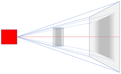
The helical microCT scan MicroCT X-ray imaging is done with a pinhole cone-beam geometry. X-rays are emitted from a very small spot – to allow high resolution – and detected by a flat rectangular X-ray camera (fig. 1). The geometry linking the source spot to the camera field of view (FOV) is actually a pyramid, but this image acquisition geometry is called “cone beam” geometry. At the upper and lower parts of the camera image, the X-ray path from source to camera is inclined at an angle called the “cone angle”. Only at one horizontal line at the camera center is this path orthogonal. This line is called the “optical axis” and is shown in red in fig.1. |
|
|
|
|
| Figure 1. MicroCT cone beam geometry: orthogonal geometry exists only at the optical axis, shown in red. |
|
|
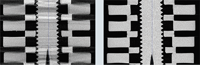
| In 1984 Lee Feldkamp, an engineer in the Ford car manufacturer, published his now-famous algorithm for reconstruction of tomography scans in cone beam geometry. This algorithm involves interpolation from inclined source-camera paths to parallel planar cross-section reconstructions. If you’re experienced in microCT you may well have published papers mentioning “Feldkamp” in the methods section. Feldkamp never claimed his algorithm was perfect; indeed he called it a “practical” cone beam method. It has an “Achilles’ heel” weakness: horizontal surfaces parallel with the midline optical axis are incorrectly reconstructed. The inclined projection data lacks sufficient information for a correct and unique reconstruction. A special phantom was devised by Michel Defrise (Brussels University) which clearly exposes this weakness in cone beam tomographic reconstruction. Figure 2 shows the microCT scan-reconstruction of this phantom in both a standard “circular” scan and a helical scan. In the circular scan the horizontal surfaces are smeared by an artefact while these surfaces are cleanly reconstructed in the helical scan. |
|
|
|
|
|
Figure 2. A circular (left) and helical (right) scan-reconstruction of the Defrise cone beam phantom.
|
 So what is the helical scan and why does it solve the “Defrise” problem? In a helical scan the sample moves axially by the distance of one pixel, at each and every rotation step of the scan. Thus each part of the object describes a helix as the sample simultaneously rotates and moves axially; by contrast during a standard “circular” scan the object parts rotate in a circle in the same plane.
There is not space here for the detailed maths involved, suffice it to say that in a helical scan, every cross-section is effectively reconstructed at the scanner’s optical axis with orthogonal geometry and free of Defrise cone angle artefacts. |
|
|
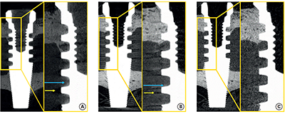
Examples of the advantages of the helical scan You may wonder why this problem of cone artefacts is not more often encountered in microCT imaging. One reason is that, in the life sciences, biological tissues and structures very rarely contain exactly flat surfaces or straight lines. This is fortuitous as it reduces the problem of cone angle artefacts. They are however encountered in material science since artificial manufactured objects very often have flat surfaces. In orthopedic research the problem is encountered when metal orthopedic screws are implanted in bone and then scanned by microCT. The artefacts from metal in the surrounding bone are partly due to the metal’s high attenuation but partly also due to flat surfaces on the screw and the Defrise effect. Recently Jung-Yoo Chesaria Choi, of the Dental Research Institute, Seoul National University School of Dentistry, Seoul, Korea, published a paper showing the compelling advantage of helical scanning in her SkyScan 1275 scanner, compared to circular scans, in the imaging and analysis of titanium implants in periodontal bone. This paper made it to the main website of the Journal of Periodontal Implant Science, where – at the time of writing – you can find a video of Jung-Yoo’s work. A figure from this paper by Choi et al (2018) is shown in figure 3. The interface between titanium implant and surrounding bone is more cleanly reconstructed in the helical scan (SkyScan 1275) than in circular scans in either the same or a different (SkyScan 1172) scanner. The paper goes on to show that “halo and blur artefacts” caused in the bone near metal surfaces were significantly reduced in helical scans compared to circular, making peri-implant osteo-integration analysis easier and better. |
|
|
|
|
|
Figure 3. A figure (7) from the described paper by Choi et al 2018 shows a comparison of coronal cross-section images. (A) A circular scan on the SkyScan 1172; (B) a circular scan on the SkyScan 1275; (C) A helical scan on the SkyScan 1275.
|
| An algorithm for exact reconstruction using the helical scan, was created by Alexander Katsevich, and this is used under license in the SkyScan scanners capable of helical scanning: the SkyScan 2211 and 2214 nano-CT instruments and the SkyScan 1275 and 1276 scanners. A Bruker microCT method note is available on helical (“spiral”) scanning – please download it from this link: MN106_Spiral Scanning.pdf
Advantages of the helical scan also include a marked decrease in ring artefacts, and also the elimination of the “Heel effect” artefact of changing attenuation with axial position in a scan reconstruction due to differential self-absorption within an xray source target. Helical scanning places a stringent demand on the accuracy and precision of sample movement during scanning, and on system geometric calibration in general. However, in terms of geometric and densitometric accuracy, it is the ideal way to do tomography. |
|
|
References Feldkamp LA et al (1084) Practical cone-beam algorithm. Josa a. 1(6): 612-9.
Chesaria Choi JY et al. (2018) J Periodontal Implant Sci. 48(4): 202-212.
Katsevich A (2002) SIAM Journal on Applied Mathematics. 62(6): 2012-26.
( https://digilander.libero.it/Spiral_CT/document/DOC_24.pdf ) |
|
|
|
|
|
Volume 6, Isue 1
January 2019
|
Bruker microCT news
|
| - Software update
We have pre-registered our users at the BrukerSupport.com for the distribution of documentation and software. Please log in your account and select your SkyScan microCT systems. You'll find the latest software downloads available for you.
If you did not receive an email for log-in, please apply for an account with your system serial number. Enjoy your membership and let us know if you have any questions!
- microCT User Meeting
The registration of the next microCT User Meeting is now opened! This year the meeting will be held in the beautiful city of Mechelen in Belgium from June 4th to 5th.
This annual meeting is a combination of global users’ talks on state-of-the-art applications in both life and material sciences and the training sessions provided by Bruker microCT. Find out more information from the website.
|
|
Upcoming events
|
| Bruker microCT will participate with an exhibit in the forthcoming conferences. Please click the link below for more information. We hope to see you there! |
|
February 02 - 05, 2019
ORS - Orthopaedic Research Society - Austin, TX, USA
February 13 - 15, 2019
iCT - Conference on Industrial Computed Tomography - Padova, Italy
February 24 - March 01, 2019
QMSKI - Quantitative MSK Imaging - Chateau Lake Louise, Canada March 19 - 22, 2019
EMIM - European Molecular Imaging Meeting - Glasgow, UK March 31 - April 03, 2019
AACR - American Association for Cancer Research - Atlanta, USA May 07 - 10, 2019
Control - International trade fair for quality assurance - Stuttgart, Germany |
|
|
|